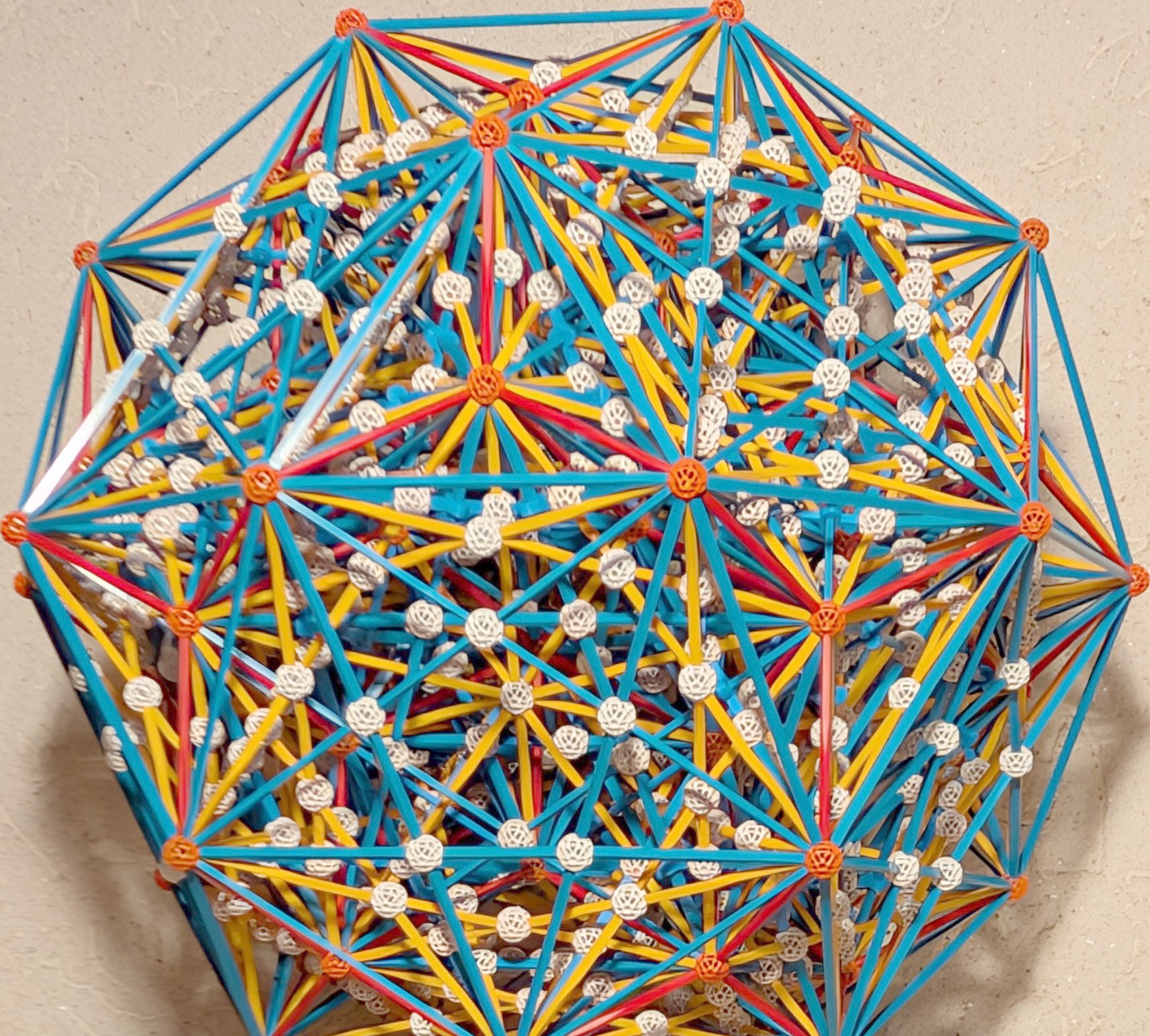
Nan Ma produced vZome models for orthographic zomeable projections of Gosset polytopes. His H3-symmetric projection (with 30 hull vertices) of the 2_31 polytope looked very appealing. The 2_31 only has 93 distinct 3D ball positions after projection. In the Zometool model, these will be represented by orange connectors. Due to the projection from 7D to 3D, a lot of edges either everlap or intersect. As bending Zometool struts is a very bad idea, all these false overlaps and intersections must be dealt with. Therefore, in the vZome model for the building instructions, all overlapping struts have been removed, and most (804) of the 1044 pairs of crossing struts have been replaced by false vertices, each connecting at least four Zometool struts. These false vertices are represented by white connectors:
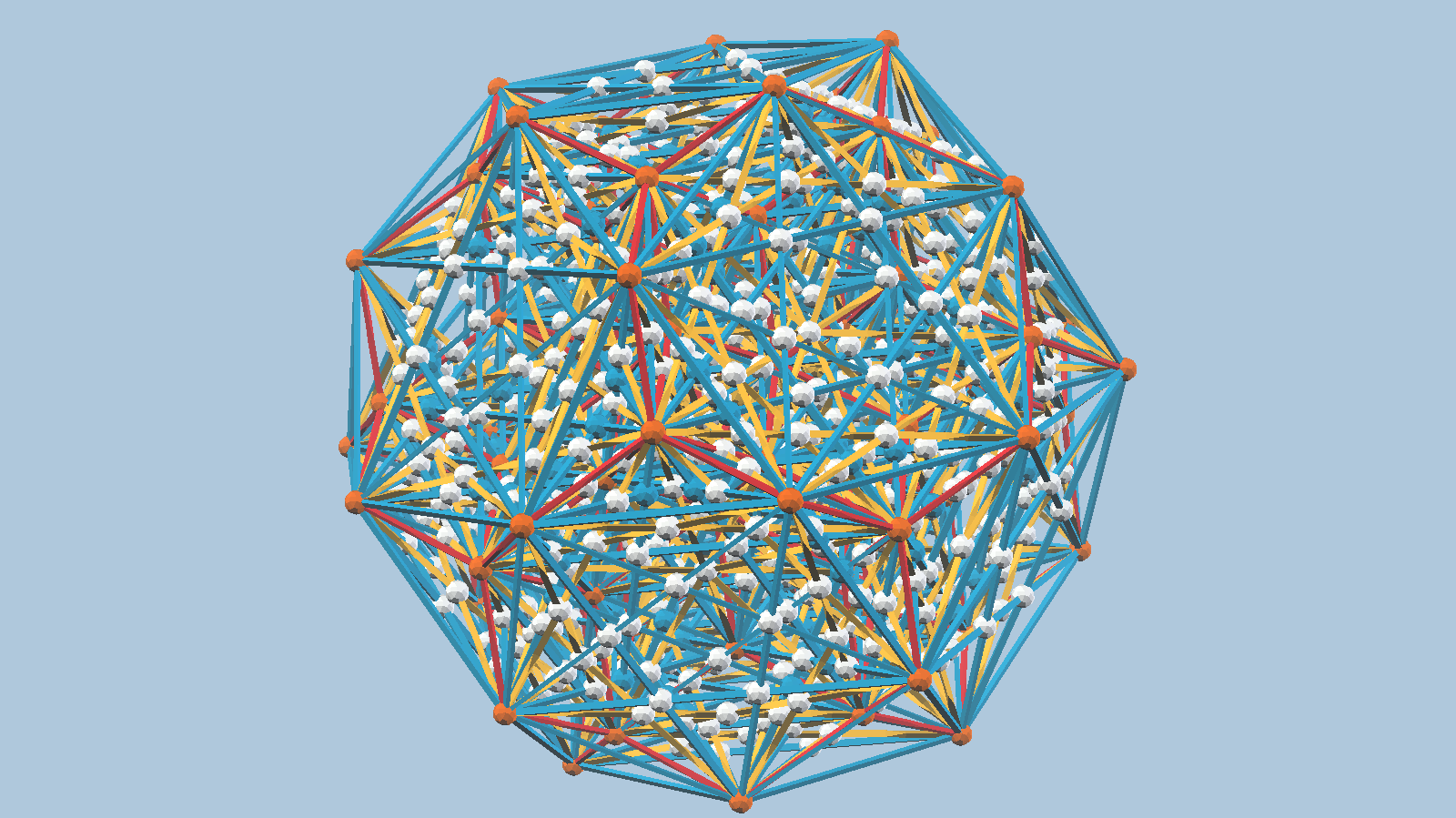
3D printing is used to handle the remaining pairs of crossing struts. In step 3, y1 struts with a hole were designed and 3D printed. These allow a regular b1 to pass through in step 4, instead of connecting y00, y0, b00 and b0 struts (indicated by yellow balls in the building instructions). The y00 and b00 struts whould have to be 3D printed and are difficult to handle.
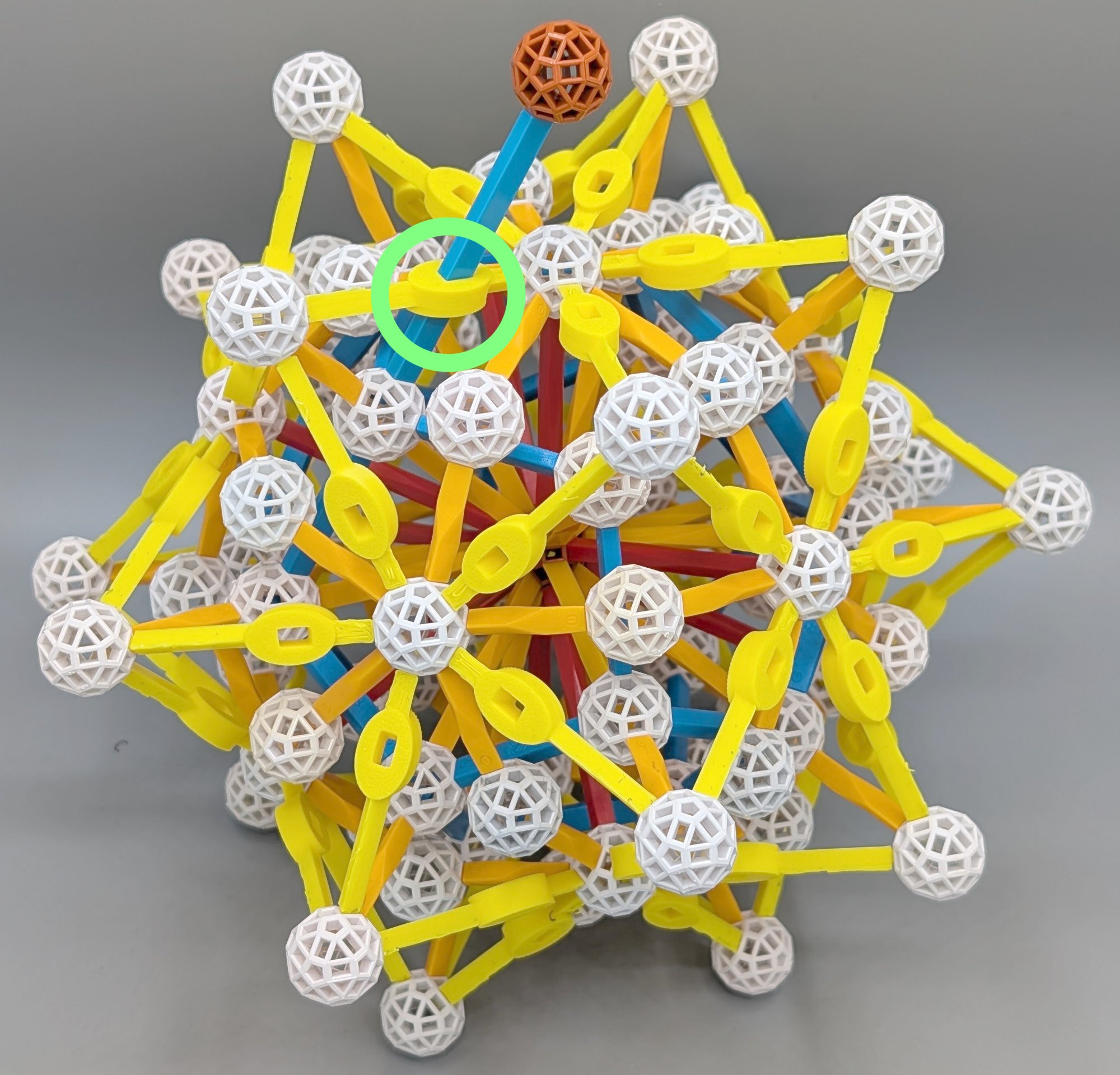
In step 13, b2 struts with a hole were designed and 3D printed. These allow a regular b3 to pass through in step 14, instead of having to connect two hb2’s and two hb3’s (indicated by teal balls in the building instructions). Both have been once produced by Zometool, but the hb3’s are rather rare.
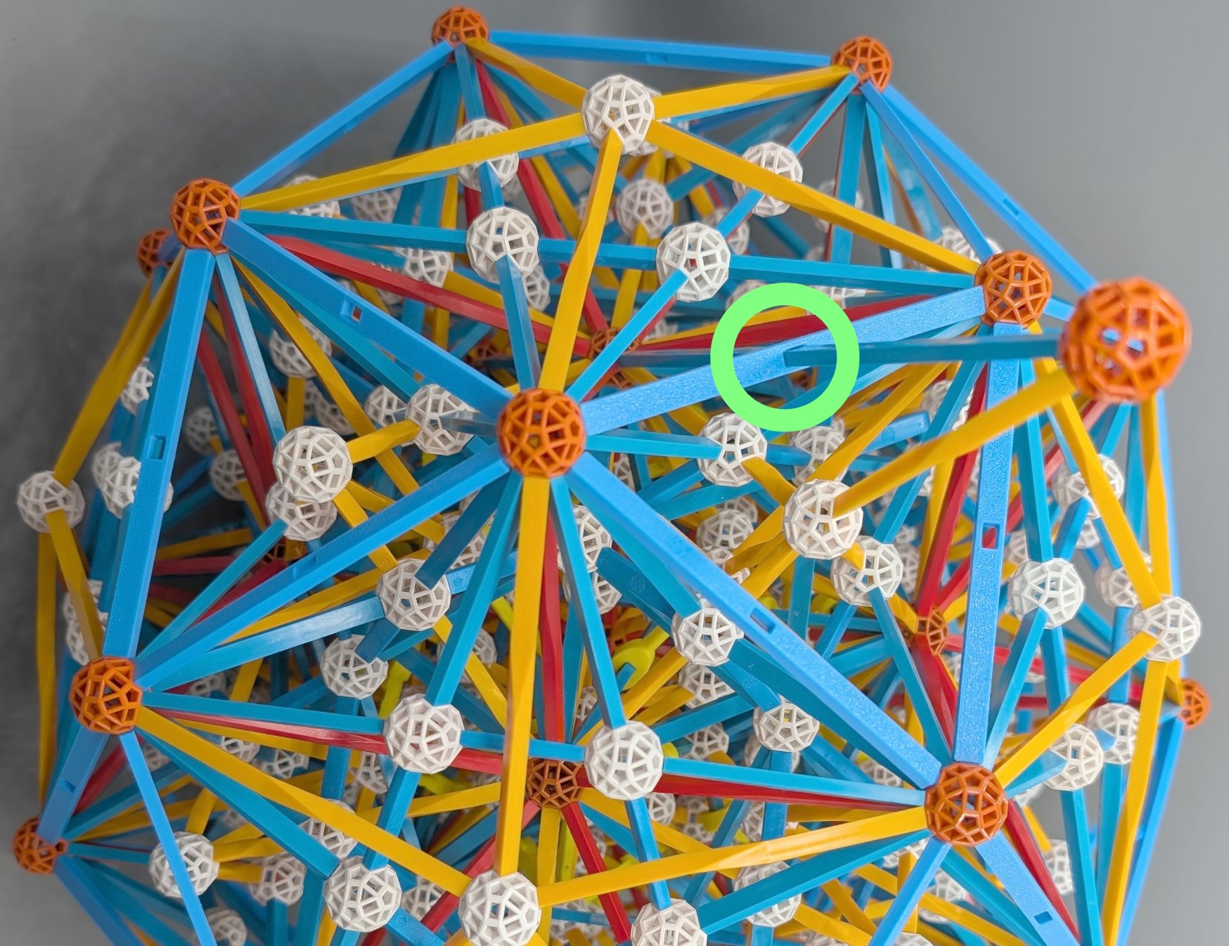
In step 18, b0 struts with a hole were designed and 3D printed. These allow a regular b2 to pass through in step 19, instead of having to connect two hb0’s and two hb2’s (indicated by teal balls in the building instructions). hb0 struts whould have to be 3D printed and are nearly impossible to handle.
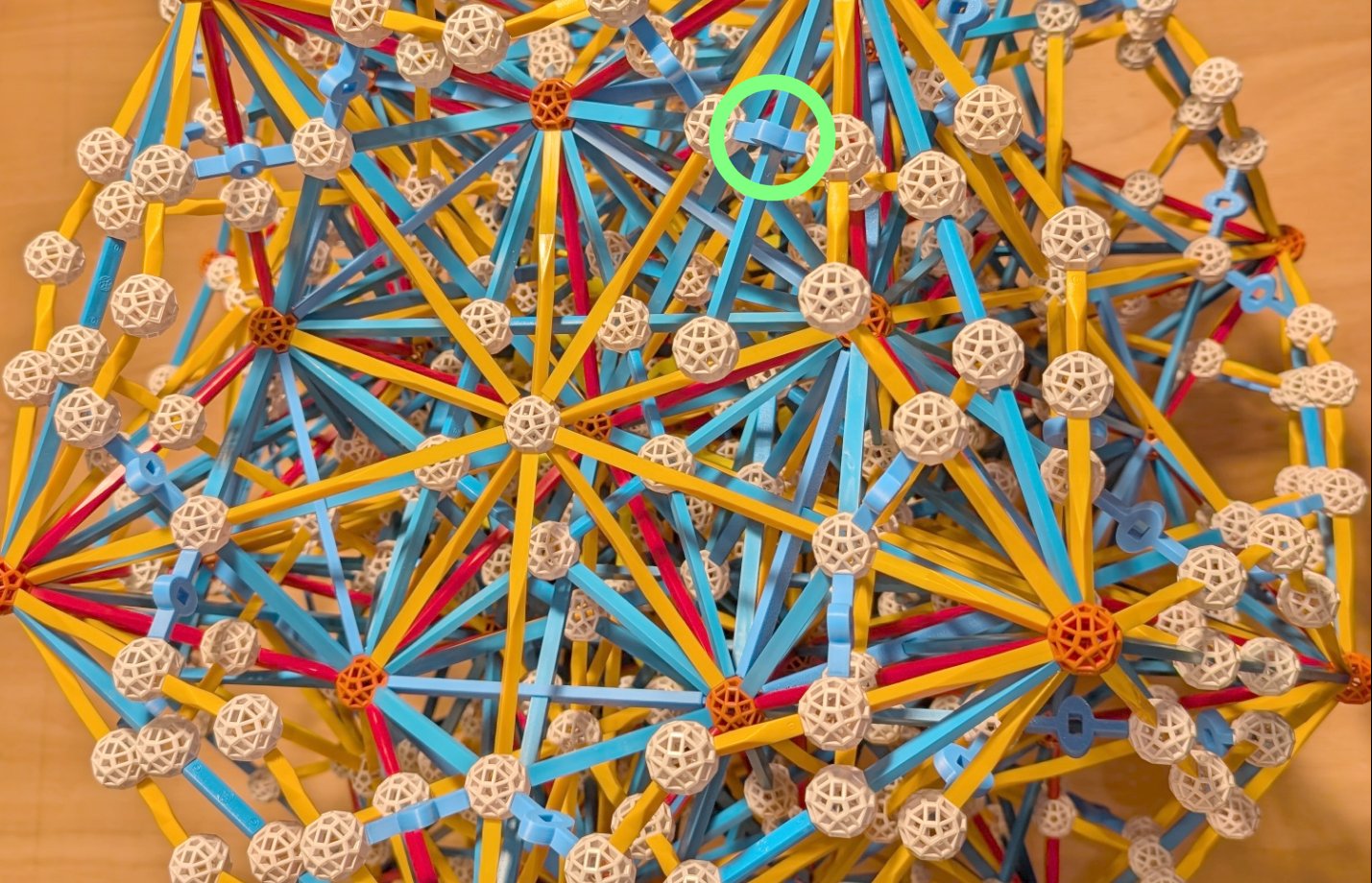
Besides these 240 3D-printed struts, the completed model requires 2894 regular Zometool struts: